
History of the Fluidhand and the VINCENTevolution
1998
Fluidhand 1
thin foil soft robot hand with 5DOF, 5iDOF
This first soft hand consists of thin foil layers, which have been joined together to form more complex drives in a sandwich construction. Five fingers, built up from 6 foil layers each, functionally welded in pairs, with the middle two foils forming the skeletal structure filled with epoxy resin. The outer two foil layers each form a fluidic muscle. For this purpose, two thin films were welded together in such a manner that chambers were formed in a row and connected to each other. When this structure is inflated with a gas or liquid, it contracts by about 20% of its length, similar to the natural muscle, and the finger curls up like a bow.

1999
Fluidhand 2
silicon tube soft sobot hand with 16DOF, 11iDOF
The new planar technology for manufacturing fluidic drives and kinematics was therefore ideally suited for actively moving miniature catheters and endoscopes. However, the forces achievable with planar film drives, which operate at a working pressure of 0.5-1 bar, were too low for the construction of an artificial hand. To generate higher grasping forces, a correspondingly higher working pressure had to act in the fluidic drives. For Fluidhand 2, “artificial muscles” based on thin silicone hoses were therefore used, which were sheathed with a flexurally flexible, stretch-resistant fabric made of polyamide.

2000
Fluidhand 3
rubber bulg soft hand prosthesis with 10DOF, 1iDOF
With the third generation of the Fluidhand, Schulz transferred the technology of flexible fluid actuators to a hand prosthesis. To achieve higher grasping forces, the drives were modified for grasping even heavy objects. The unfolded silicone tubes reinforced with fabric were replaced by miniature folded bellows, which in turn were encased in fabric and attached to aluminum joints in the folds by nylon threads to keep their shape. Three drive elements in each finger, with the two distal bellows coupled together, and two drives in the thumb allow 14 joint axes to move in this hand, equivalent to 14 DOF at 10 iDOF. The fluid actuators were driven by means of miniature hydraulics. The control system, consisting of pump, valve, electronics, sensors and tank, was connected to the prosthesis via a hose approximately 1 m long. The hydraulic unit was the size of a portable telephone and was worn on the belt.

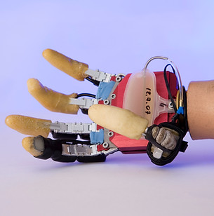
2001
Fluidhand 4
rubber bulg soft hand prosthesis with 10DOF, 6iDOF
The Fluidhand 4 has 10 flexible bellows drives, each of which, when pressurized, angles an aluminum joint by 90 degrees. Stretching is achieved by suction of the drive medium and by additional elastic bands. Each long finger has two drives that are fluidically coupled to each other and each leads to a common control valve in the metacarpus. The thumb has two individually movable drives, each of which is actuated by a separate valve. The drive medium is water. This hand prosthesis operates hydraulically for the first time. A miniature pump draws the fluid from an elastic reservoir in the forearm and pumps it at up to 6 bar via the valve bank into the bellows drive chambers. The pump and valves are controlled by a microprocessor in the hand, and the prosthesis wearer gives the control commands via myoelectric sensors.
2002
Fluidhand 5
rubber bulg soft handprosthesis with 8DOF, 5iDOF
The Fluidhand 5 was designed with the aim of integrating all system components of miniature hydraulics into the metacarpals in order to make the hand compatible with established socket systems. The prosthesis can be connected to all standard prosthetic sockets via a quicksnap wrist. Both the myoelectric sensors and the energy storage of the socket are used. The pump, fluid tank, valve bank and controller are located in and on the metacarpus. With the reduction in tank size, the number of fluidic drive was reduced to 8. The ring finger and little finger are flexed over one drive each. In the weight-optimized frame in sandwich construction, the elastic finger abduction was integrated. Five valves control the 8 drives of the hand, with the ring, little and middle fingers being hydraulically connected to each other.

2003
Fluidhand 6
rubber bulg soft handprosthesis with 4DOF, 3iDOF
The Fluidhand 6 is a particularly compact version of the hydraulic hand prosthesis, reduced to the essentials. The index, middle and ring fingers are each moved in the base joint via a flexible bellows drive, the little finger is mechanically coupled to the ring finger, and the middle finger is hydraulically coupled to the ring finger. The thumb is actuated in the basic joint. In this way, the thumb and index finger can be moved separately, while the other fingers move together. The 4 drives are controlled by a 3 valve bank, the miniature pump sucks distilled water from a pressure storage tank to pump it into the drive chambers. The weight of the hand is about 350 g. The aluminum fingers were covered with a PU foam. In the basic joints, all long fingers have an elastically mounted abduction.

2004
Fluidhand 7
rubber bulg soft handprosthesis with 8DOF, 8iDOF
The Fluidhand 7 is designed as an experimental hand. It is used to develop new control methods and to test a new tank system that is capable of storing energy. The hand therefore has one valve for each of the 8 drives. A type of spring accumulator was developed for the hydraulic tank, which allows the hand to be closed quickly and silently without the hydraulic pump operating. Due to the large number of new and experimental components, the metacarpus has turned out to be significantly larger than the previous model, but at this stage of development, the anatomical shape and size of the hand is not a priority.

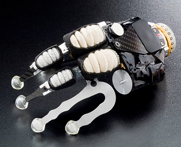
2005
Fluidhand 8
rubber bulg soft handprosthesis with 8DOF, 4iDOF
The Fluidhand 8 has 8 drives that are controlled via 5 valves. The bellows in the index finger and middle finger are each hydraulically coupled with each other, and the drives of the ring and little fingers are also connected with each other via a common valve. The special feature of this further development is that the metacarpus has been replaced by a hermetically sealed pressure body. Inside the metacarpus is an elastic tank in the form of a diaphragm, in which both the drive medium (vegetable oil) and the control electronics, valves and pump are integrated; all system components "float" permanently in the drive medium. Between the pressure body shell and the diaphragm there is again a two-phase gas with a constant pressure of 2 bar.
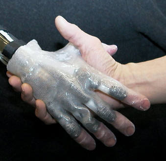
2006
Fluidhand 9
rubber bulg soft handprosthesis with 5DOF, 5iDOF
The Fluidhand 9 has 5 drives of different sizes. The base joints of the index finger and middle finger are equipped with stronger drives. The elastic fluid tank is located in the wrist. When the fingers are emptied, they are stretched and the fluid is pumped from the finger joints into the elastic tank in the wrist, bending the wrist and opening the hand further. The pump is noise-isolated and free-swinging in a CFRP tank; valves and controls are located in the metacarpus, which is completely covered with CFRP. The thumb with a drive in the base pivots between flat hand and opposition position to the three-point grip.